VIDYUT YANTRA UDYOG
GST : 09AMXPG1075C1ZY

call images

Call us

Waveguide Variable Attenuators

Waveguide Variable Attenuators

MOQ : 5 Pieces

Waveguide Variable Attenuators Specification

  • Input
  • Waveguide Flange
  • Power Source
  • Manual
  • Components
  • Moving vane/iris, Precision waveguide body, Adjustment knob
  • IP Rating
  • Not Rated
  • Features
  • Low insertion loss, Precise attenuation setting, Durable body, Easy adjustment
  • Response Time
  • Instantaneous mechanical adjustment
  • Power Supply
  • Manual Operation (No power required)
  • Resolution
  • 0.1 dB
  • Operating Temperature
  • -20C to +60C
  • Interface
  • Waveguide flange (UG/CPR type as per model)
  • Display Type
  • Mechanical scale, Analog (Graduated scale)
  • Output
  • Waveguide Flange
  • Usage
  • Laboratory, Telecommunications, RF Testing, Microwave Systems
  • Product Type
  • Waveguide Variable Attenuator
  • Application
  • Test & Measurement, Calibration, Production and R&D
  • Rated Voltage
  • N/A (Passive device)
  • Size
  • Standard waveguide sizes available (e.g., WR-90, WR-75)
  • Dimension (L*W*H)
  • Approx. 175 mm x 110 mm x 80 mm
  • Function
  • Attenuation of microwave signals in waveguide systems
  • Color
  • Metallic Grey / Silver
  • Weight
  • Approx. 1.2 kg (varies by model)
  • Capacity
  • Attenuation up to 30 dB (model dependent)
  • Frequency
  • Upto 18 GHz (Band Specific)
  • VSWR
  • 1.2:1 maximum
  • Attenuation Range
  • 0 to 30 dB (Standard); Custom ranges available
  • Max Input Power
  • Typically up to 2 W CW (depends on model)
  • Operating Band
  • Designated by waveguide size (e.g., WR28: 26.5-40 GHz)
  • Attenuation Accuracy
  • 0.3 dB typical
  • Finish
  • Silver anodized or powder coated
  • Service Life
  • Designed for extended, high-cycling use
  • Calibration
  • Individually calibrated and labeled
  • Mechanical Drive
  • Manual adjustment knob or screw drive
  • Attenuator Type
  • Rotary vane or Slab type
  • Material
  • Aluminum alloy or Brass, with conductive finish
  • Connector Type
  • Waveguide flanges (fitted as required)
  • Storage Temperature
  • -20C to +70C
 

Waveguide Variable Attenuators Trade Information

  • Minimum Order Quantity
  • 5 Pieces
  • Payment Terms
  • Cash in Advance (CID)
  • Supply Ability
  • 100 Pieces Per Month
  • Delivery Time
  • 7 Days
  • Main Domestic Market
  • All India
 

About Waveguide Variable Attenuators


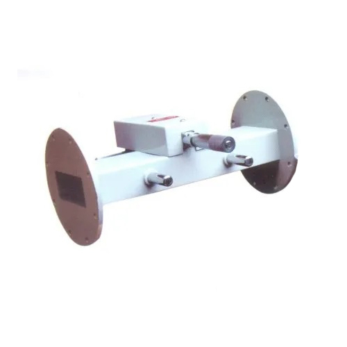
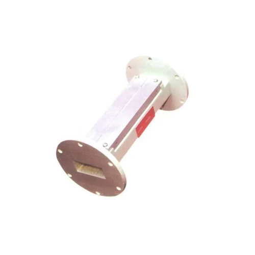
Step into the spotlight with our Waveguide Variable Attenuators, now in the trending sale of top-drawer RF components. Imposing in precision and renowned for durability, these attenuators deliver attenuation from 0 to 30 dB (custom ranges available) with impressive accuracy of 0.3 dB. Constructed in aluminum alloy or brass with a conductive, silver anodized finish, they ensure reliable performance for laboratory, telecommunications, and RF testing applications. Featuring manual rotary vane or slab type adjustment, and calibrated scales, these are the preferred choice for high-cycling, professional environments across India.

Engineered for Versatility and Precision

Waveguide Variable Attenuators are meticulously designed for attenuation of microwave signals, making them essential in test & measurement, calibration, production, and R&D applications. Suitable for laboratories, telecommunications, and advanced microwave systems, these passive devices feature a robust aluminum alloy or brass construction, ensuring durability and a low insertion loss. The adjustable, user-friendly manual operation allows for real-time, analog graduated scale readings, ideal for professionals seeking accuracy in demanding environments.


Packaging Details, Sample Options, and Supply Terms

For every outlay, our packaging ensures safe delivery: attenuators are secured in sturdy, protective cartons or customized foam-lined cases for precision components. We support our customers by offering sample units upon request, so you can evaluate the product before making a larger commitment. Supply is facilitated across major Indian FOB Ports, and our asking price structure offers you competitive choices based on your volume needs.


FAQ's of Waveguide Variable Attenuators:


Q: How is the attenuation adjusted on the Waveguide Variable Attenuators?

A: Attenuation is set manually using a rotary vane or slab adjustment knob or screw drive, allowing precise control with instant response and fine resolution up to 0.1 dB.

Q: What are the typical applications for these waveguide attenuators?

A: They are ideal for laboratory experiments, telecommunications, RF testing, microwave system development, and R&D projects needing precise microwave signal attenuation.

Q: When is it beneficial to use a calibrated attenuator?

A: Calibrated attenuators provide reliable, repeatable attenuation values, which are invaluable for sensitive test and measurement tasks where accuracy is paramount.

Q: Where can I use these attenuators regarding frequency range and waveguide size?

A: These attenuators are band-specific, compatible with standard waveguide sizes (e.g., WR-28, WR-90), and are designed for frequency ranges up to 18 GHz (model dependent).

Q: What are the main benefits of the material and finish used for these attenuators?

A: The aluminum alloy or brass body with a conductive, corrosion-resistant finish ensures both mechanical durability and minimal signal degradation, supporting extended, high-cycling use.

Q: How is the device packaged and supplied to customers?

A: Devices are packaged in durable, shock-resistant cartons or cases, and samples are offered. Supply uses major Indian FOB ports, and competitive pricing is available based on order volume.

Tell us about your requirement
product

Price:

Quantity
Select Unit

  • 50
  • 100
  • 200
  • 250
  • 500
  • 1000+
Additional detail
Mobile number

Email

More Products in Variable Attenuator Category

Variable Attenuators

Variable Attenuators

Minimum Order Quantity : 5 Pieces

Thermal Conductivity : Standard

Input : RF/Coaxial Connector (BNC/Ntype/SMA optional)

Size : 94 x 28 mm

Features : Low VSWR, precision attenuation, durable metal body, compact size

Weight : Approx. 80g

Coaxial Fixed Attenuators

Coaxial Fixed Attenuators

Minimum Order Quantity : 5 Pieces

Thermal Conductivity : High, with efficient heat dissipation

Input : Coaxial RF input, up to 18 GHz

Size : Standard sizes; e.g., 40 mm length x 20 mm diameter

Features : Low VSWR, wide frequency range, precision attenuation, robust construction

Weight : Approx. 4060 grams (varies by model)

Waveguide Fixed Attenuators

Waveguide Fixed Attenuators

Minimum Order Quantity : 1 Piece

Thermal Conductivity : High Thermal Stability for Microwave Loads

Input : Waveguide Interface

Size : Varies by Model (e.g., WR90, WR62, etc.)

Features : Low VSWR, Precision Attenuation, Wide Frequency Range

Weight : Depends on Model (typically 200g 800g)

Coaxial Detector Mount

Coaxial Detector Mount

Minimum Order Quantity : 5 Pieces

Thermal Conductivity : High (Aluminum body for heat dissipation)

Input : Mechanical (Detector fixing)

Size : Standard (see Dimension)

Features : Adjustable mount, robust build, corrosionresistant finish, easy installation

Weight : Approx. 200 g


Back to top